Steps to Install a Conventional Fire Alarm System
Step 1: Cabling Routing & Device Installation
Route the fire-rated cabling between device locations in accordance with the zone map (and any other external equipment) and back to the panel location as indicated in the system design drawings. Each cable should be clearly labeled with its function, i.e. zone 1, etc.
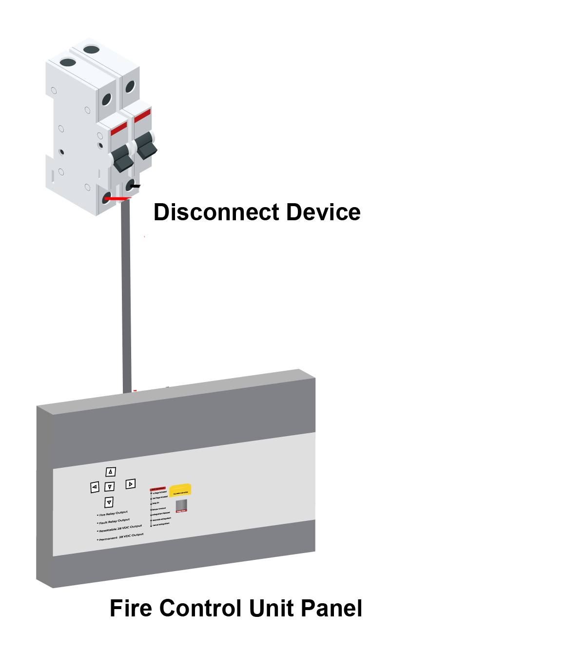
Step 2: Connect the main supply
A readily accessible disconnect device should be incorporated external to the equipment.
Step 3: Connect zone circuit to the panel
A Manual Call Point (a device that enables personnel to raise an alarm in the event of a fire incident by pressing a frangible element to activate the alarm system) is wired before detectors as seen in the diagram below.

After a Manual Call Point is connected, you proceed by connecting the Heat fire and smoke detectors as seen below.
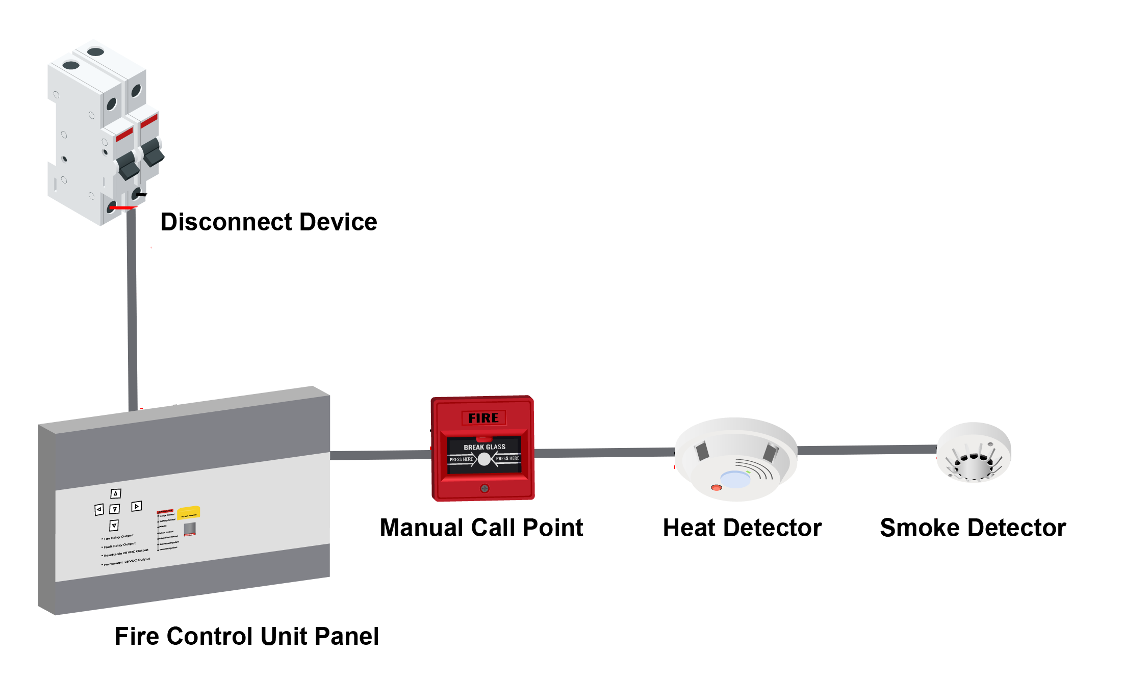
A zone will end by connecting the smoke fire detector. Note: As a zone terminates by the smoke detector you must remove EOLR (end of line Resistor) from the terminal block and fit to the last detector i.e. smoke detector.
Repeat these steps for each zone in the building.
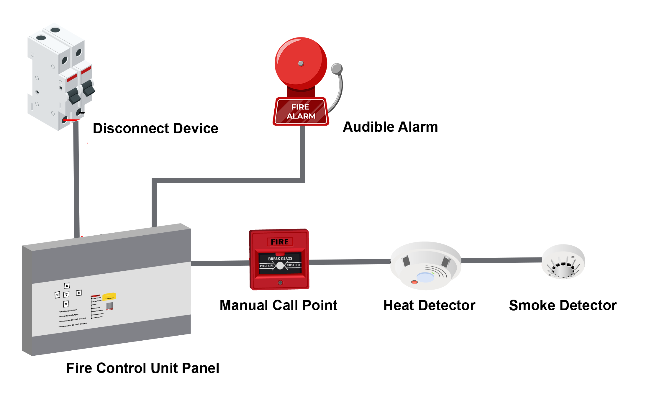
Step 4: Connect sound alarm circuits to the panel
Connect the sound alarm to the control panel. Place the sound alarm in locations around the building so they can be clearly heard by everyone.
Step 5. Connect the visual display to the system
Connect the visual alarm to the control panel. Like the sound alarm, place the visual alarms in different locations around the building so they can be clearly seen by everyone.

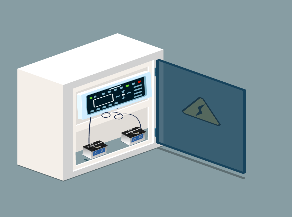
Step 6. Connect battery supply to power up the panel
The diagram below illustrates the positioning of the batteries as an integral part of the Fire Control Unit Box. Batteries allow the alarm system to operate during a power outage.